boardcad-le
BoardCAD is an easy to use CAD/CAM-program that allows you to quickly design your own surfboards. BoardCAD LE is a fork of the original BoardCAD project where a few things have been removed to make it leaner and easier to maintain.
BoardCAD user guide
Introduction
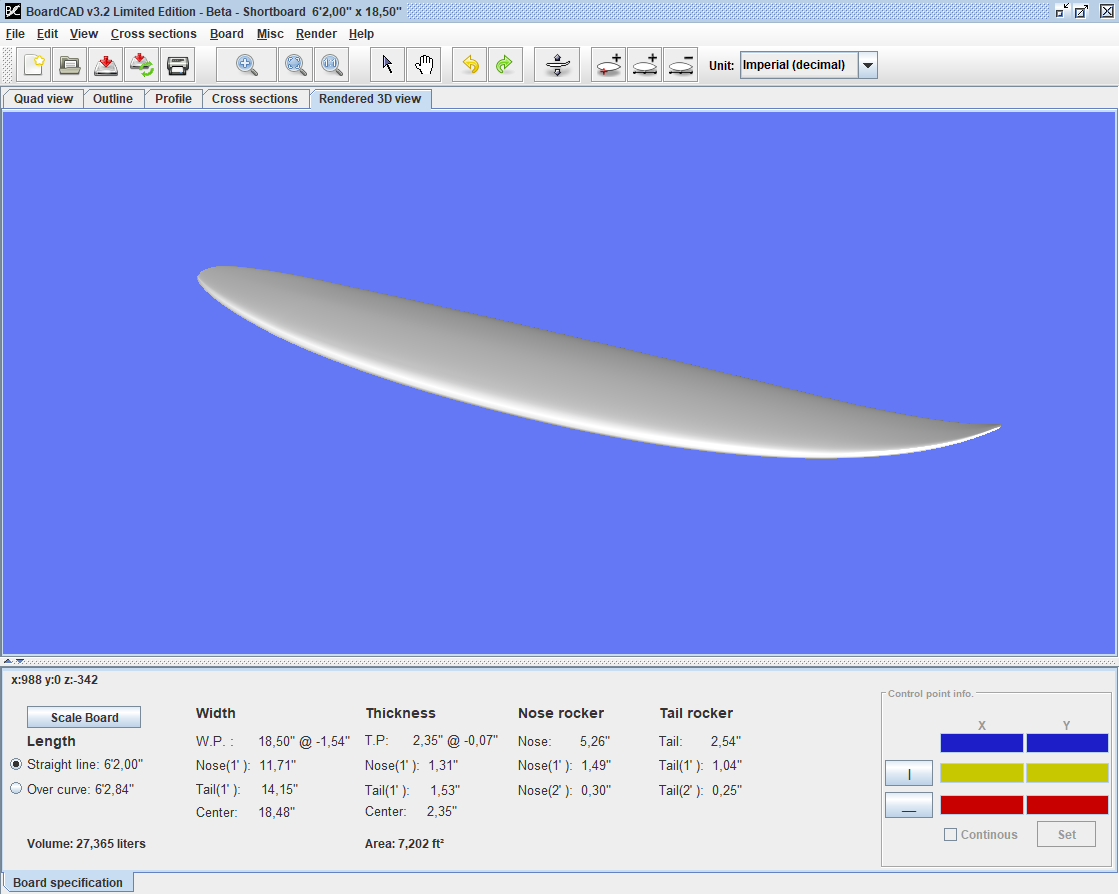
BoardCAD is an open source CAD/CAM-system for surfboards. It is aimed at making the design process easy and intuitive, allowing the designer to be creative and play with different designs. The result can be visualized in 3D for quick feedback. BoardCAD allows the shaper to print full scale templates or have the board CNC-machined. A board can only be validated in the water, but knowing exactly what has been changed between different boards allows the shaper to learn more from each of them. BoardCAD doesn’t make you a good shaper, but used in the right way it can help the inexperienced progress faster and the seasoned to become more productive. Start with the quick tutorial to get a feeling for the overall workflow and the functionality available, then go more in detail. For information on how to download and install BoardCAD see downloading and installing. For more general information about the project and contributing see contribute.
EDITING
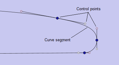
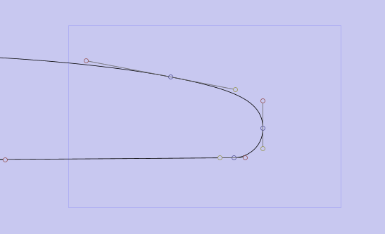
The outline, rocker and cross sections are defined using composite bezier curves. The curves consist of bezier curve segments which are defined by the blue end points which the composite curve passes through and the yellow and red tangent control points which define the direction and ‘velocity’ of the curve at the endpoints and thus the shape of the segment. The endpoints can be set to continous using the control point info, this ensures that the tangents of the previous segment and the next have the same direction making the curve smooth across the control point.
There are three different ways to edit the curves: mouse, keyboard and through the control point info user interface.
Editing using the mouse
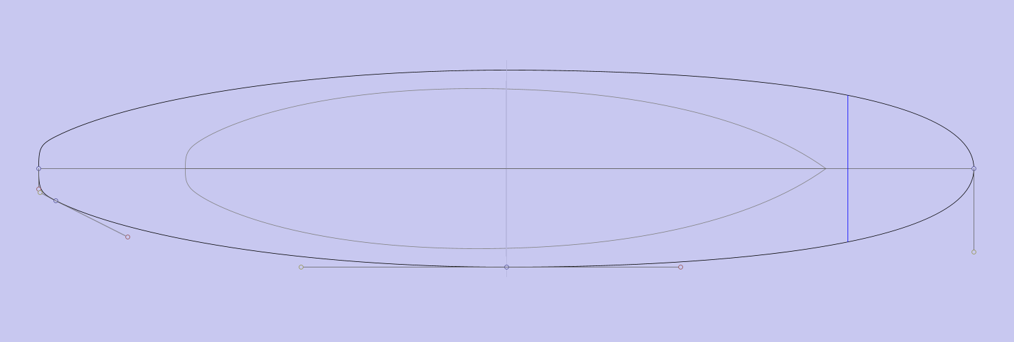
The curves can easily be edited by clicking on a control point and dragging it using the mouse. Multiple control points can be selected by either dragging a box around them or holding down CRTL while selecting multiple blue control points. Moving multiple control points can be useful f.ex. to maintain the same outline curve when adjusting the width of a board, maintaining the rail shape when adding concave or vee or maintaining nose and tail thickness when adjusting rocker.
Use the quad view to keep an overview of the entire board while editing, or select the individual profile, outline and cross sections tabs for more detailed view with less visual noise. While editing the coordinates of the mouse is displayed in the top left corner of the view and the control point positions are updated in control point info. While editing you can zoom using the zoom mode in the tool bar and dragging a box around the area you want to zoom on, or you can use the scroll wheel on the mouse to zoom. To pan the view, use the pan mode in toolbar or click and hold the scroll wheel and drag to pan. Click fit in the toolbar to fit the curves to the view after panning and zooming or use spot check from the right click menu to quickly view the entire curves without loosing you zoom and pan and continue working on the part of the board. Additonal control points can be added using the right click menu in the view or the toolbar. Click on the curve to add the control point. Note that the curve will remain the same after adding a control point. Control points can be removed in the same manner. Note that the curve is not guaranteed to remain the same after removing a control point. It’s advicable to use no more control points than neccasary to define the curves your after as curve segments are smoother than the composite curves. When editing cross sections you can select different cross sections by clicking on the position of the cross section on the outline. Cross sections can be added, moved and removed from the right click menu. You can also copy and paste cross sections. If you intend to have the board CNC’d using other software than boardCAD you should take particular care of not moving control point too extreme between cross sections and keeping the same number of control points on each cross section. Undo/redo can be done on every change you make to the curves. The number of operations you can undo is only limited by available memory.
Editing using the keyboard
There are numerous ways to edit the control points using the keyboard. You can move the selected control point with the arrow keys and A(left), S(right), D(up) and F(down). You can press once to nudge the control point or hold the key down for larger movements. To make a tangent longer press E (extend), make it shorter by pressing R(retract). To rotate the control point clockwise press W, to rotate it counterclockwise press Q. By holding down the ALT key you can make fine adjustments as every editing operation 1/10th of normal movement. Holding down ALT can also be combined with mouse editing for fine precision when dragging the points with the mouse. The H key hides/shows the control points to view the curve without the noise of the control points. Press the < key to cycle through the tangents and endpoint point (yellow, blue and red) at a location. Press the C key to cycle through the control points of a curve. Control points can be deleted using the delete key. Press +/- to cycle through cross sections. Press B to toggle deck/bottom/both in the profile view Use CTRL Z and Y to undo and redo editing. Use CTRL S to save the board.
| Hotkeys | Function |
|---|---|
| arrow keys, A S D F | Move control point |
| E R | Extend and Retract tangent |
| Q W | Rotate tangent clockwise / counterclockwise |
| ALT | Fine adjustment |
| H | Hide / show control points |
| < | Cycle yellow / blue / red control points |
| C | Cycle control points of composite curve |
| + - | Cycle cross sections |
| B | Cycle deck / bottom /both |
| CTRL Z CTRL Y | Undo / Redo |
| CTRL S | Save board |
Setting position from control point info
Exact coordinates can be in the respective edit boxes in control point info in the lower, right corner. This can be useful if you want to set a control point exactly to measurements, or f.ex. want two control points to have the same vertical position. Click the set button to apply the values.
Design aids
Under the View-menu you’ll find a list of different design aids that can be switched on and off. While all are useful, having all visible at the same time clutter the workspace creating visual noise and make it difficult to edit the board.
When designing a new board it is common to get some inspiration from other designs, by copying for example the outline, or just comparing the current design with other designs. Depending on what you have at hand, this can be done in different ways. If you already have the model of the other board you can load the board and show it in the background as a Ghost board. If you have the physical board you can take take measurements and add those as guide points. If you have a picture of the board you can use that as a template by displaying the picture in the background.
Ghost board
A ghost board can be loaded in the background to compare designs. The ghost board can be scaled to the same size as the current board using the command “scale ghost to current board size” in the board. The ghost board can be moved by holding down G (brings it into focus) and using the arrow keys, and rotated using the Q an W hotkeys. This makes it possible to use the ghost board much like a physical template.
Background image
A background image can be loaded in every view. The background image can be positioned by holding down T and clicking on the tail of the image, and holding down N and clicking on the nose of the image.
Guide points
Guidepoints can be added by clicking the “Add guide point button” and directly insert the point in the selected view by clicking, or you can open the Guide points table either via the Board menu or the right click menu. Once the table is open you can directly edit any existing guide points by double clicking. By right clicking the mouse you can choose to add new guide points via (x,y) coordinates or you can remove highlighted guidepoints.

- Shows a grid in the background. Depending on whether the unit is set to metrics or imperial, the distance between each grid-line is set to 1 cm or 1 inch respectively.
- Shows ghost board in the background. See ghost board.
- Shows the curves of the current board before they were edited.
-
Show the control points that allows the curve to be edited. By hiding these no editing can be done to the curve, but viewing the curve without any visual noise can be useful.
- Show all cross section simultaneously in the cross section view.
- Show Guide points. See guidepoints.
- The curvature is a measure of how far from flat a curve is. For a flat line the curvature is equal to zero, and for other curves the curvature is equal to the inverse of its radius at every point. This means that if the curvature of the rocker is equal to zero, the rocker is totally flat at that point, and if it goes below zero it means that the board has negative rocker.
- Shows much volume each part of the board has.
- This shows the volume center
- The sliding info gives information about the width and thickness of the board at the point where the mouse is placed.
- Shows the cross section at the point where the mouse is placed.
- Shows fin position
- Shows a background image if such image is loaded. More info on backgroud images can be found in chapter 4.
- Using anti-aliasing smoothens the jagged lines that occurs due to the low resolution of computer screens.
- Shows a zero-line under the board
- Shows the distance over the bottom tail, from the tail and the nose, to the current mouse position.
- Shows where the cross sections are placed.
- Shows the flow of the rail at 30, 45, 60, and 90 degrees
- Shows the tucked under
- Shows rocker and width of board at tail, nose, center, one-foot-off and two-foot-off. 3.2 Setting visual appearance By choosing Misc, Settings, in the menu you get a dialog window where it is possible to configurate the visual appearance of the board model and all the design aids described above. The dialog window has three tabs.
- In the size and thickness you can control the size of the control points and the line thickness of the board model.
- A number of different configurations that didn’t fit under the other tabs. Look and feel lets you set the appearance of the GUI, in order to give BoardCAD either a platform independent look and feel like Metal or a native look and feel that make BoardCAD look more like a native application and less java-like. Print guide points, and Print fins, configures whether those will be visible when printing board information sheets or templates. The fraction accuracy configures to what fraction of an inch that measurements will be shown, when imperial units are used. Default value is 16, i.e. 1/16 of an inch. If Use Rocker Stick Adjustment is turned on, the rocker will be adjusted so the center tangent is level. This is similar to the industry standard way of measuring rocker with a rocker stick. Offset interpolated cross sections by rocker means that the cross sections will be drawn in their full 3D-position rather than flat. This is especially useful when comparing the rail of the 3D-model with the rail of drawn in the 2D-view.
- Let you set the color of the board model and the different design aids.
Input values
Inputs that take measurements can take the various formats regardless of the selected unit f.ex imperial (ex. 6’10” or 3 1/4”), meters (ex. 0.5m), centimeters (ex. 50.5cm), or millimeters (ex. 2200mm). If no unit is specified, the current unit will be used. For imperial the input value will be inches.
Other useful features
- There is a sliding info bar for measurements at any given point along the length of the board. In it, you can also show over curve measurements which makes it possible to get accurate measurements at any given point over the bottom curve. Very useful to get measurements as exactly as possible as it’s hard to measure on the actual blank unless you measure over the bottom curve. On the other hand, if you look at these measurement with regards to the x position the difference is not that big.
- You can view the curvature of the board to ensure that the curve is smooth. In particular around a control point the curvature graph may be discontinous. This may be visible in a cut board or a template. The curvature graph can also be used to analyze the curves beyond what is otherwise possible visually. Note that the sliding info for bottom shows the radius of the curvature at any point which is also useful for analyzing the curvature of the rocker. Curvature can be compared between boards by loading a ghost board, when G is pressed the curvature of both the current board and the ghost board are shown (if ‘show curvature’ is selected).
SETTING
Preferences
BoardCAD is intended to be used by anyone who is interested in designing surfboards. Different users have different needs and preferences. BoardCAD is configurable, you can adjust colors, line thickness, look and feel and turn features on and off. BoardCAD also support different languages.
Choosing Bezier interpolation
It is possible to configure how the cross sections are interpolated in the Bezier model. This affects the form of the sliding cross section, if you have chosen to view this and how the 3D model is generated. The two methods should give similar results, but cross section interpolation gives best result if all cross sections have the same number of control points, S-blend interpolation is more reliable when different number of control points are used.
Setting language
The language of the menus in BoardCAD can be changed under the menu Misc, Language. Currently six languages are supported: English, French, Portuguese, Spanish, Norwegian, and Dutch. You will need to restart BoardCAD for the changes to appear.
PRINTING
Board templates can be printed in full scale. In addition a spec sheet page can be printed or saved to an image file. Printing to pdf is currently not supported, but a virtual pdf printer can be used to generate pdf files.
Printing spec sheets
You can print a spec sheet by clicking the “Print spec sheet” icon in the toolbar, or from the submenu Print in the File menu.
Printing templates
When printing templates, the margins should be adjusted to the absolute minimum your printer can handle to minimize the amount of paper used. The difference between a wide and narrow margin can be the difference between one and two strips of paper being used. If you loose data in the print, adjust the margins up. Note that printers may distort the image when print due to the paper feeding mechanism being inaccurate. It is recommended that you check the accuracy against the grid where each square should be an inch.
Printing sandwich templates
Printing HWS templates
EXPORTING MODELS
BoardCAD supports exporting to several different file format. The board can be exported in 3D in the formats stl to be cut by most standard CNC machines. This is not neccesary for surfboard specific cutting services as they will be able to cut from a .brd file. The board profile and template can also be exported in two different dxf formats to be used for cutting foam block with a hotwire cutter or cutting templates.
STL
STL is a file format native to the stereolithography CAD software created by 3D Systems. This file format is supported by many other software packages and is widely used for rapid prototyping and computer-aided manufacturing. An STL file describes a raw unstructured triangulated surface, a triangulated model of the board is exported, i.e. the surfaces are converted into lots of small triangles. This makes the model hard to edit when imported in another CAD-system. However, as long as the model will not be edited further the triangulated models work fine.
DXF
AutoCAD DXF (Drawing Interchange Format, or Drawing Exchange Format) is a CAD data file format developed by Autodesk for enabling data interoperability between AutoCAD and other programs. DXF-files can be exported 2D for the outline, rocker, and cross sections for creating templates.
CNC